RANDOM PAGE
SITE SEARCH
LOG
IN
SIGN UP
HELP
To gain access to revision questions, please sign up and log in.
AS
A2
Logic Circuits and Boolean Expressions
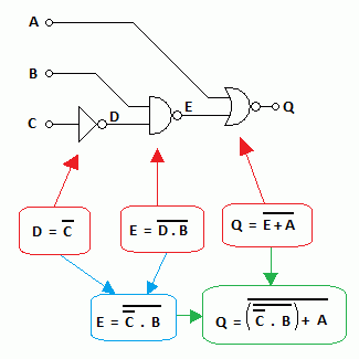
This example is typical of AS exam questions which can be asked in four ways ...
- Given the boolean expressions, produce the circuit diagram and truth table.
- Given the circuit diagram, produce the boolean expressions and truth table.
- Given the truth table, produce the boolean expressions and circuit diagram.
- If Q is one when all the inputs are zero except for B, produce the truth table, the circuit diagram and the boolean expressions.
To understand this, you need to have a fair knowledge of the basics.

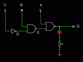
For the Falstad Circuit Simulation, CTRL+Click Example Logic Circuit
In options, check European Resistors and uncheck Conventional Current.
Click the logic inputs and watch the output change
Alternatively view Logic_Circuit.txt.
Save or copy the text on the web page. Import the saved or copied text into the Falstad simulator.
Here is the new HTML5 Simulator Site.

Creating the Truth Table
A  B  C     D     E     Q
0  0  0     1     1     0
0  0  1     0     1     0
0  1  0     1     0     1
0  1  1     0     1     0
1  0  0     1     1     0
1  0  1     0     1     0
1  1  0     1     0     0
1  1  1     0     1     0
- Columns A, B and C count in binary from 0 to 7.
- This ensures that every combination of zeros and ones is present and in a sensible order.
- Column D (NOT Gate):
- This is produced by inverting column C (NOT Rule).
- The zeros become ones and the ones become zeros.
- Column E (NAND Gate):
- Look at columns B and D.
- Locate where two ones give a zero (NAND Rule).
- This happens in only two rows.
- All the other rows can be filled with ones without further thought.
- Column Q (NOR Gate):
- Look at columns A and E.
- Locate where two zeros give a one (NOR Rule).
- This happens in only one row.
- All the other rows can be filled in with zeros without further thought.
Q is ONE when all the inputs are zero except for B.
reviseOmatic V3
Contacts, ©, Cookies, Data Protection and Disclaimers
Hosted at linode.com, London


